Turn on suggestions
Auto-suggest helps you quickly narrow down your search results by suggesting possible matches as you type.
Showing results for
- Republic of Gamers Forum
- Motherboards
- Previous Generations
- Other Motherboards
- Clarkdale coldbug mod for Max III Extreme
Options
- Subscribe to RSS Feed
- Mark Topic as New
- Mark Topic as Read
- Float this Topic for Current User
- Bookmark
- Subscribe
- Mute
- Printer Friendly Page
Clarkdale coldbug mod for Max III Extreme
Retired
Not applicable
Options
- Mark as New
- Bookmark
- Subscribe
- Mute
- Subscribe to RSS Feed
- Permalink
06-23-2010
01:57 PM
- last edited on
03-05-2024
06:47 PM
by
![]() ROGBot
ROGBot
Ok lets start off with the usual disclaimer.
***Asus nor myself are not to be held reponsible for damages to your motherboard and or any other hardware etc etc etc. Overclocking and modifications will void your warranty***
Now that thats out of the way I made a tutorial of modding this particular board.
Lets start off with where the mod happens. This little chip reads .75X K nominally.
For the mod we want it to read 0K or basically have continuity between both sides of the chip, which basically means we need to solder across it. I chose a diff route for those that may want a "removable" mod.

Same chip just a shot from a diff angle.
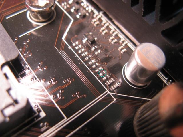
Now for those curious this is how you determine which chip is required to mod. Set your mutimeter to test continuity place probe on one of these pins and probe around......I already did this for you however.

Rather than just bridge the gap of the resistor I soldered a wire to each end and moved them to a remote easily acessible location.

I soldered both ends to an old fan header I had lying around and used hot glue to fix all wires in place so as to keep them from being disturbed. I double checked to make sure nominal open resistance was still correct.

The purpose for the fan header makes it easy to turn the mod OFF and ON with just using a spare jumper I had lying around.

And a final shot of the completed mod.

Enjoy and i hope some people find this usefull.
***Asus nor myself are not to be held reponsible for damages to your motherboard and or any other hardware etc etc etc. Overclocking and modifications will void your warranty***
Now that thats out of the way I made a tutorial of modding this particular board.
Lets start off with where the mod happens. This little chip reads .75X K nominally.
For the mod we want it to read 0K or basically have continuity between both sides of the chip, which basically means we need to solder across it. I chose a diff route for those that may want a "removable" mod.
Same chip just a shot from a diff angle.
Now for those curious this is how you determine which chip is required to mod. Set your mutimeter to test continuity place probe on one of these pins and probe around......I already did this for you however.
Rather than just bridge the gap of the resistor I soldered a wire to each end and moved them to a remote easily acessible location.
I soldered both ends to an old fan header I had lying around and used hot glue to fix all wires in place so as to keep them from being disturbed. I double checked to make sure nominal open resistance was still correct.
The purpose for the fan header makes it easy to turn the mod OFF and ON with just using a spare jumper I had lying around.
And a final shot of the completed mod.
Enjoy and i hope some people find this usefull.
Labels:
- Labels:
-
Other Motherboards
9,219 Views
2 REPLIES 2
Options
- Mark as New
- Bookmark
- Subscribe
- Mute
- Subscribe to RSS Feed
- Permalink
06-24-2010 08:27 PM
This is for sure nice! the only thing that suck is that so many people don't know how to weld and will pierce the mobo XD Don;t worry I know how to do it;) Great work here carry on my friend!!
Martin_metal_88

Colenzo :Coolermaster ATCS 840 | Gigabyte's EP55-UD5 | Intel Core I7 860 @ 3.8Ghz | 4GB G.skill Trident 1600 | MSI GTX460 1GB HAWK Twin frozr | WD 640 black + WD 1TB green + WD 1TB Blue | Pionner DVR-216 | Silverstone Strider Plus 850W | Coolermaster Hyper 212 plus in push pull fan config |
Ask for more!
Options
- Mark as New
- Bookmark
- Subscribe
- Mute
- Subscribe to RSS Feed
- Permalink
07-04-2010 02:17 PM
Shortly after making this post a user sent me a pm on another forum asking if the ln2 mode jumper does not already do this without needing a hardmod........the answer is I am not quite sure what the ln2 mode jumper does at a hardware level however leaving mod in OPEN mode and putting jumper in ln2 mode on position does NOT change the resistance value to 0K.

Once i get a chance to put the board on ln2 I will play with various combinations with both "jumpers" ( the one i added and the ln2 mode ) and let you know my thoughts on it.
Once i get a chance to put the board on ln2 I will play with various combinations with both "jumpers" ( the one i added and the ln2 mode ) and let you know my thoughts on it.
