Turn on suggestions
Auto-suggest helps you quickly narrow down your search results by suggesting possible matches as you type.
Showing results for
- Republic of Gamers Forum
- Motherboards
- 3D Printing
- 3D printing gone wrong by ASUS
Options
- Subscribe to RSS Feed
- Mark Topic as New
- Mark Topic as Read
- Float this Topic for Current User
- Bookmark
- Subscribe
- Mute
- Printer Friendly Page
3D printing gone wrong by ASUS
Options
- Mark as New
- Bookmark
- Subscribe
- Mute
- Subscribe to RSS Feed
- Permalink
01-28-2017
10:46 AM
- last edited on
03-05-2024
10:53 PM
by
![]() ROGBot
ROGBot
Hello,
Let me start with saying that the 3D printing is cool. But at this point ASUS looks like a amateur with the way they do this.
Let's say I wanna 3D print some parts for the TUF Z270 MARK 2. Let's grab the M.2 fan holder(short) and download it. I got 2 files and on each file there is 1 part inside. part 1 is the standoff, the other one is the fan holder. It's already unclear for me why there are 2 separated files, because without the standoff you cannot mount the M.2 fan holder (vice versa). Now it's seems like ASUS want you to print them separately, but in fact you should consider this as just one part and treat it like this. WTF!
Does ASUS even get informed about these thing?! Because you cannot do it like this! The M.2 fan holder(short) should be seen as one product, so give it as one part! When you separate it into 2 parts for people to customise there should also be an assembly of the 2 parts (so 3 files in total!). When you do it differently you just being a dumb-ass! And you can easily fit a .txt file with a simple explanation.
For customising these parts it's always a good idea to share more then one filetype (.SLDPRT, .DXF etc.). Asus is a big company who sells al over the world so this is something they have to keep in mind.
For customising I actually only need the standoff file, because from that part I can make my own thingy to mount a fan. But when I open the file in Solidworks the part is facing the wrong way. Same issue with the ''Custom nameplate''. I want to add a name to the ''Custom nameplate'' but when I open the file it's facing the wrong way. These parts have a front/back/left/right etc, and for the draftsman this is the basis. So it's really weird that this is even an issue.
And why didn't ASUS included the .STL filetype. With windows 10 people will have a the 3D builder app and they can actually see the product. With the .STP file they can't. And include a sheet with dimensions so everybody knows the sizes and they don't have to measure them self's.
I actually think this is a really good idea from ASUS. But we are talking about ASUS, A big company who is a top leader with there products and they simply fail in giving me a decent drawing to start with. And they put this on the official ASUS website! It's pathetic and they should be ashamed!
Labels:
- Labels:
-
3D Printing
-
FDM
-
SLA
-
SLS
20,195 Views
4 REPLIES 4
Options
- Mark as New
- Bookmark
- Subscribe
- Mute
- Subscribe to RSS Feed
- Permalink
01-28-2017 05:50 PM
Well this answers some of my questions of why the 3D file for the 3 slot HB SLI cover has 3 different files named in sizes that makes no sense to me.*


“Two things are infinite: the universe and human stupidity, I'm not sure about the former” ~ Albert Einstein
Options
- Mark as New
- Bookmark
- Subscribe
- Mute
- Subscribe to RSS Feed
- Permalink
01-28-2017 06:20 PM
I'm thinking the downloadable ASUS part models are translated directly (and poorly?) off their factory part specs. The factory needs to have full spec for each hole, cut, bend, press, and fold - they gotta mass-produce the parts on mass-production tools with mass-production tolerances - they don't print their parts, they use machining, cast, and mold processes which aren't readily available outside of industry. So consumers with 3D printers seem to sort of be left to fend for themselves, I guess the assumption is that if you purchase a 3D printer then you must automatically be a master at using 3D design software to "correct" flaws in the templates?
"All opinions are not equal. Some are a very great deal more robust, sophisticated and well supported in logic and argument than others." - Douglas Adams
[/Korth]
[/Korth]
Options
- Mark as New
- Bookmark
- Subscribe
- Mute
- Subscribe to RSS Feed
- Permalink
01-30-2017 12:37 PM
This has nothing to do with any factory specs or tolerances. These drawings are not draw the way they should have been drawn. Let say this was a hobbyist or something...
I will show you a few exemples why ASUS are amateurs! I'm using Solidworks 2015, this is a professional CAD drawing program. When you upload the ''custom nameplate'' you have no name in it. So its a clean surface where everybody can put a name on it without any problems.
When I open the file this is my front view (first picture). So I have to go to the bottom view to see the front of the custom nameplate (second picture). I put a name in it, but I have no idea if this is done correctly. Why? Because I can turn the custom nameplate 180 degrees! So how do I know that the name is not going to be upside down when I mount it?! There is no information about this, only a small picture where I downloaded the files from.
If the draftsman is already in the fault with not showing correctly the front, then I can not know/trust that the left/right/bottom/top is also correct.


Example 2
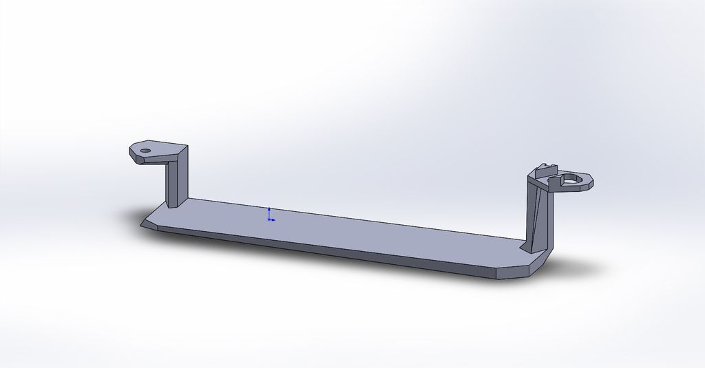
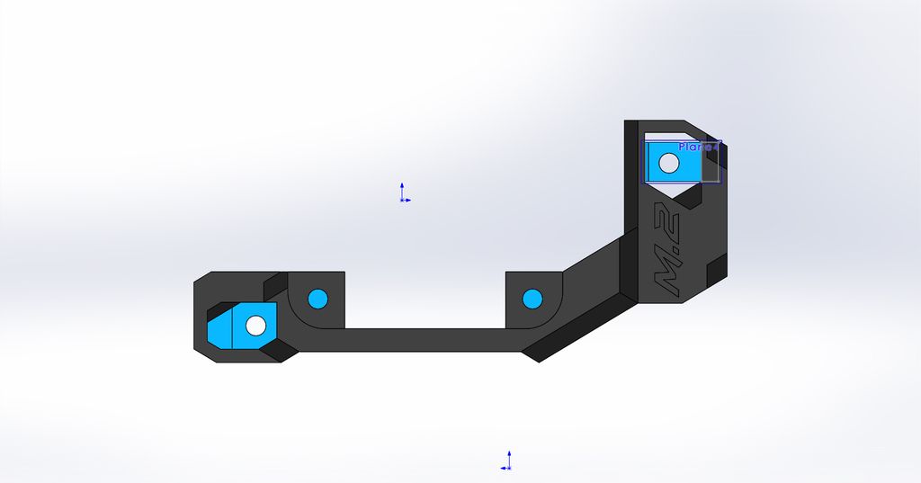
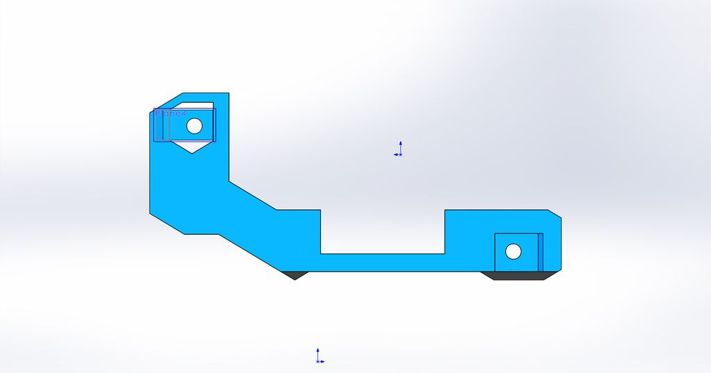
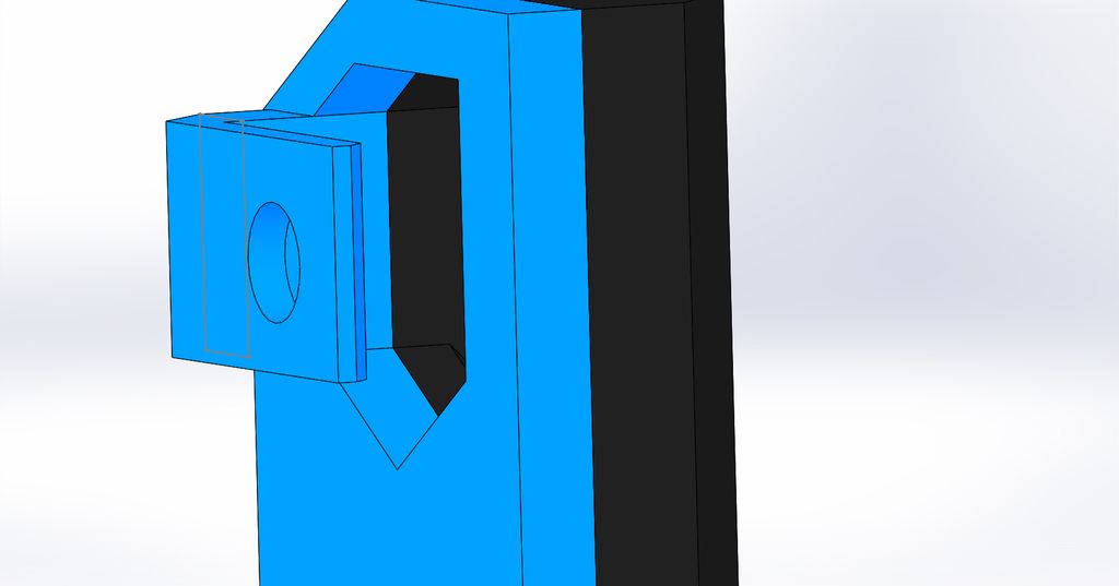
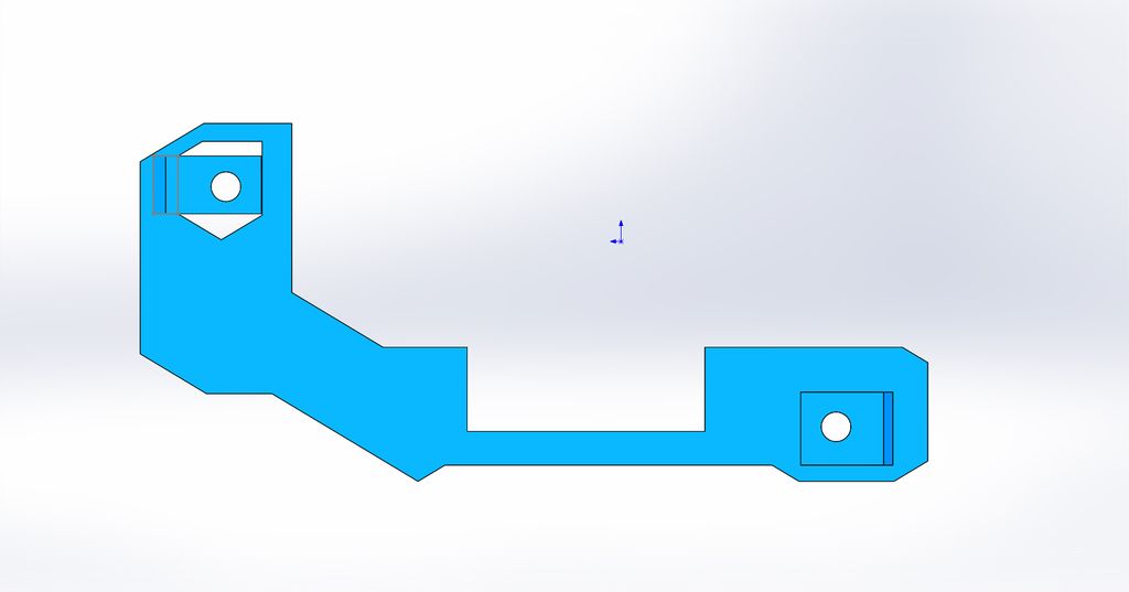
This is the M.2 fan holder(short). I had to assembly the 2 parts and I also gave them different colours so you can understand my story.
The M.2 fan holder(short) is being showed correctly with the front showing the front, there are no edges that protrude so this is good!
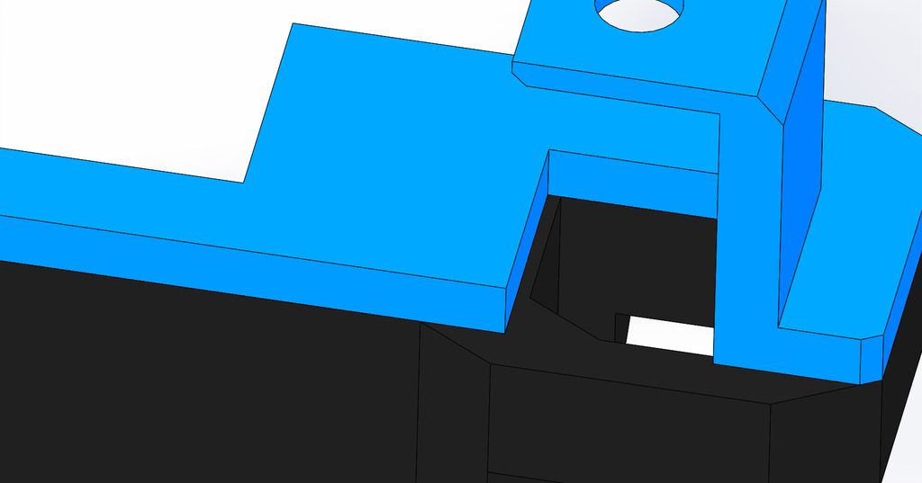
I go the the backview and there you can already tell the difference, the bleu part is not inline with the black part. The edges protrude.
Oké... I can already hear a few guys thinking. What does it matter?! Well, a good draftsman is consistent in his way of drawing. So If you follow the edges of the part you are going to apply this everywhere! But now there are a few lines that not match up with the other part. There is no reason for the draftsman to deviate from the original plan and do it differently on these small pieces.
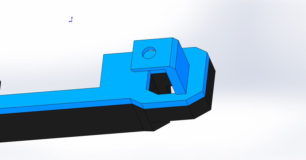
This is how it should have looked. The 2 parts fit perfectly together without any edge proturde.
I will show you a few exemples why ASUS are amateurs! I'm using Solidworks 2015, this is a professional CAD drawing program. When you upload the ''custom nameplate'' you have no name in it. So its a clean surface where everybody can put a name on it without any problems.
When I open the file this is my front view (first picture). So I have to go to the bottom view to see the front of the custom nameplate (second picture). I put a name in it, but I have no idea if this is done correctly. Why? Because I can turn the custom nameplate 180 degrees! So how do I know that the name is not going to be upside down when I mount it?! There is no information about this, only a small picture where I downloaded the files from.
If the draftsman is already in the fault with not showing correctly the front, then I can not know/trust that the left/right/bottom/top is also correct.
Example 2
This is the M.2 fan holder(short). I had to assembly the 2 parts and I also gave them different colours so you can understand my story.
The M.2 fan holder(short) is being showed correctly with the front showing the front, there are no edges that protrude so this is good!
I go the the backview and there you can already tell the difference, the bleu part is not inline with the black part. The edges protrude.
Oké... I can already hear a few guys thinking. What does it matter?! Well, a good draftsman is consistent in his way of drawing. So If you follow the edges of the part you are going to apply this everywhere! But now there are a few lines that not match up with the other part. There is no reason for the draftsman to deviate from the original plan and do it differently on these small pieces.
This is how it should have looked. The 2 parts fit perfectly together without any edge proturde.
Options
- Mark as New
- Bookmark
- Subscribe
- Mute
- Subscribe to RSS Feed
- Permalink
01-30-2017 01:10 PM
I'm guessing the nameplate was face down because that's the orientation they expect you to use for printing.
I agree that the two parts not lining up doesn't make sense. I wonder if there were multiple revisions and they accidentally included files from two different versions.
I agree that the two parts not lining up doesn't make sense. I wonder if there were multiple revisions and they accidentally included files from two different versions.
A bus station is where a bus stops. A train station is where a train stops. On my desk, I have a work station…
Related Content
- Asus ROG Maximus Z790 hero eva-2 edition xmp issues in Intel 700 & 600 Series
- games crashing when xmp is on in Intel 700 & 600 Series
- Mainboard Z690 Maximus Extreme (Mar-2022) with BSOD - exception violation // memory errors // etc in Intel 700 & 600 Series
- Asus ROG Crosshair VIII Formula Q-code 00 in Other Motherboards
- rog strix z790-H does not boot with XMP enabled in Intel 700 & 600 Series
