[Computer Chassis] ROG Hyperion GR701 chassis front panel ROG logo disassembly and assembly precautions
Notice
1. Kindly wear gloves to protect your hands before proceeding with disassembly or assembly. Pay special attention to the corners of the parts to avoid any scratches.
2. When the side panel or front panel is made of glass, please handle it with extreme care during disassembly to avoid any collisions, falls, or undue stress.
3. When disassembling, please lay the casing flat on a stable surface to prevent the side panel from falling during the process.
4. Kindly ensure that the relevant wires are neatly arranged during assembly to prevent any damage to the wires throughout the process.
5. Keep track of all screws and small components during disassembly and assembly to avoid losing any parts.
Tools required
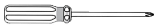
1. Phillips screwdriver PH2
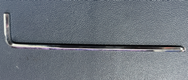
2. Hex wrench 4mm
1. Remove the left/right glass side panels

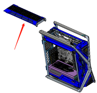
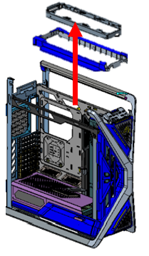
2. Remove the upper filter assembly
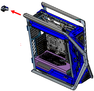
3. Remove the left upper handle
3-1 Remove the upper left handle back cover.
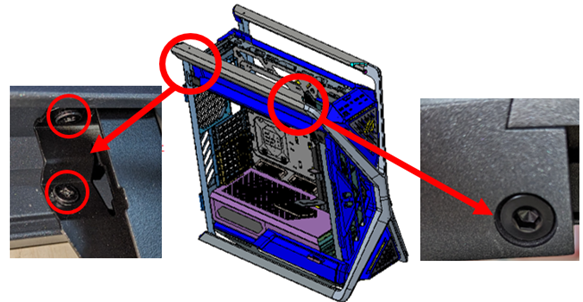
3-2 It is necessary to remove 3 fixing screws (1 pc) on the upper handle and front panel and 2 fixing screws (2 pcs) on the rear of the case.
4. Remove the 3 screws in the picture to remove the upper cover base and upper cover water-cooling rack.
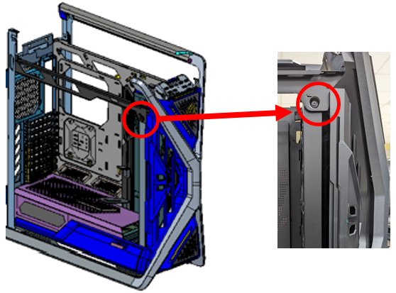
5. Remove the functional compartment components, open the functional compartment, and remove the 2 screws in the picture.
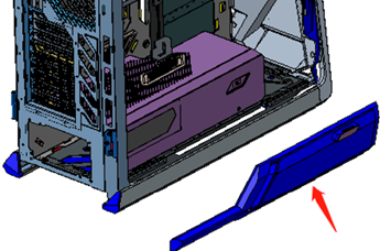
6. Remove the front fan/water cooling rack (you need to remove 1 screw in the picture) and place it inside the fuselage.
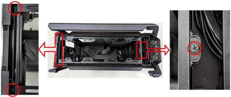
7. Remove the FIO module
7-1 Remove the 2 screws on the FIO upper cover
7-2 Remove the FIO upper cover

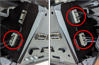
7-3 Remove the cable connected to the left/right side of the FIO
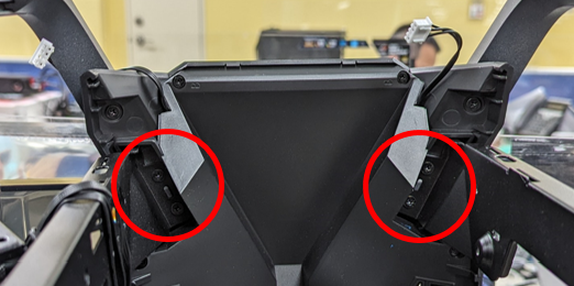
7-4 Remove the fixing screws on the left and right sides of the FIO module to dismantle the module.
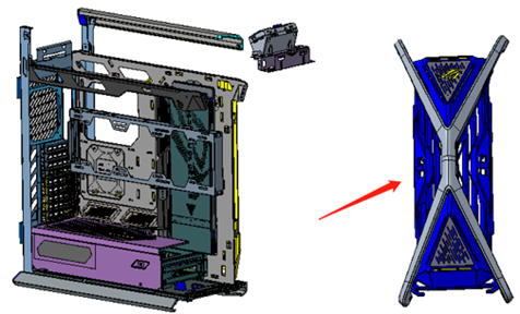
8. Remove the front panel assembly
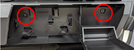
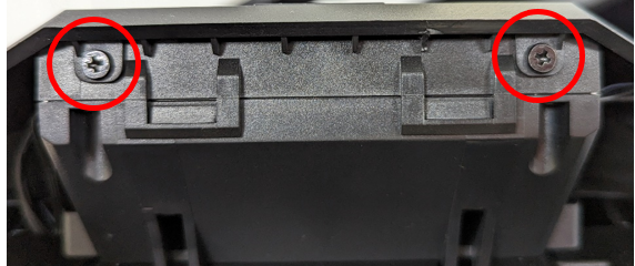
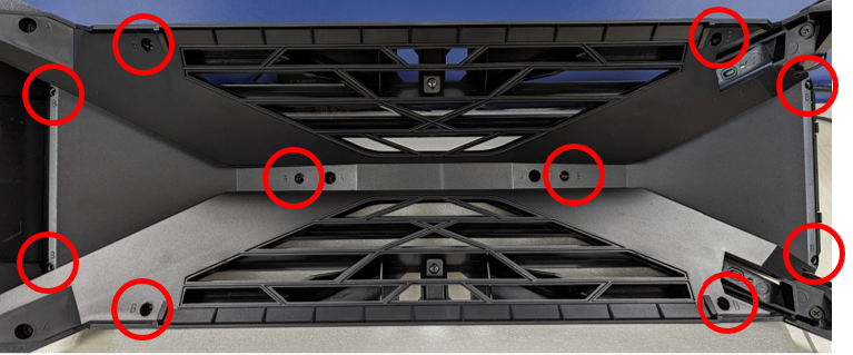
8-1 Remove the fixing screws on the front panel and the top of the fuselage, 2 on each side (red circle in the picture below)
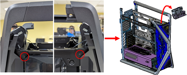
8-2 Remove the 6-corner fixing screws on the front panel and the bottom of the fuselage, 1 on each side (as shown in the picture below), and then the front panel can be removed
9. Remove light panel
9-1 Remove the 10 screws marked position B (as shown in the red circle in the picture below) and remove the inner cover.
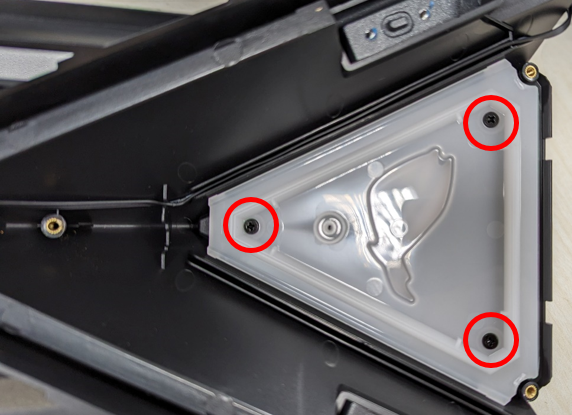
9-2 Remove the screws marked in the red circle to remove the light panel and complete the replacement.

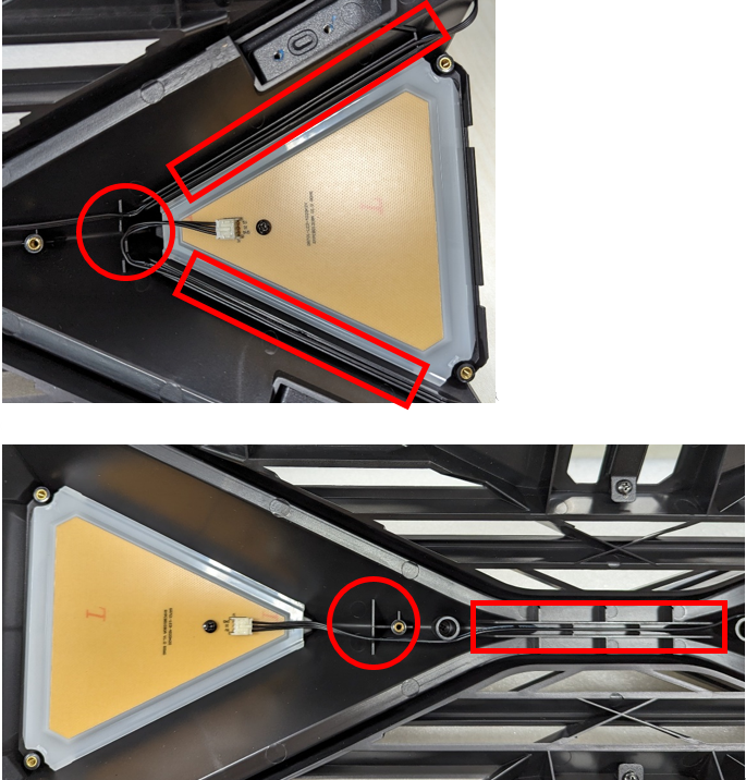
9-3 After installing the light panel, please be careful to put the wires into the wire trough (as shown in the red box in the picture) to avoid breaking the wires when the front panel is installed on the chassis.
If you need to clean ROG LOGO, please refer to the following steps
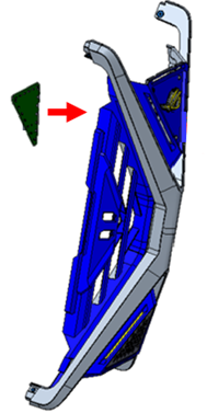
1. With the light panel removed, remove the screws marked in the red circle to remove the triangular light guide plate and ROG LOGO.
2. 2. When assembling ROG LOGO/triangular light guide plate/light panel, please pay attention to the following matters.
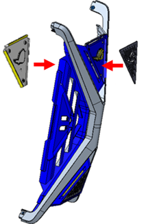
2-1 Cover the ROG LOGO from the front, then cover the triangular light guide plate from the back, and lock the 3 screws.
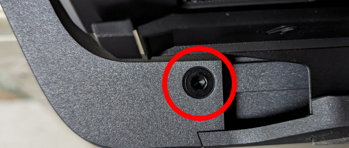
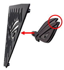
* When assembling the ROG LOGO, please pay attention to the convex surface of the LOGO (red circle in the picture below) aligned with the direction of the LOGO metal plate for installation.
2-2 Finally, install the light panel and lock the screws