The Kaby Lake overclocking guide
Conroe, Sandy Bridge, Ivy Bridge, Haswell, Skylake, and anything in between, we’ve overclocked them all. Each had their pros and cons, but the standout architecture in that list is Sandy Bridge. Good samples were capable of achieving stable overclocks of 5GHz on air cooling. It’s a landmark that has proven elusive, until now. Finally, we have a worthy successor: Kaby Lake. Intel's latest processors make 5GHz overclocks possible with air cooling, and you even can go beyond that. No need for lengthy intros when excitement levels are at fever pitch. Let’s get down to business!
Frequency expectations – i7-7700K
Our R&D dept has tested hundreds of CPUs and found the following frequency ranges are workable for overclocking Kaby Lake i7-7700K CPUs:
- 20% of samples are stable with Handbrake/AVX workloads when running at 5GHz CPU core speeds.
- The AVX offset parameter can be used to clock 80% of CPU samples to 5GHz for light workloads, falling back to 4.8GHz for applications that use AVX code.
- The ASUS Thermal Control Tool has now been ported into UEFI and can be used to configure profiles for light and heavy (non-AVX) workloads to extend CPU core overclocking margins on air and water cooling by up to 300MHz.
- Memory frequency: The best CPU samples can achieve speeds of DDR4-4133 with four DIMMs (ROG Maximus IX series of motherboards needed). DDR4-4266 is possible on the Maximus IX Apex. For mainstream use, we recommend opting for a memory kit rated no faster than DDR4-3600, as all CPUs are capable of achieving such speeds.
CPU power consumption and cooling requirements
One of the questions that always arises when we’re dealing with overclocking is "how much Vcore is safe?" Generally, we recommend constraining an overclock to stay below 2 X the stock power consumption of the processor under full load. To work out what that figure is, we can measure the CPU’s power draw via the EPS 12V power line using an oscilloscope and current probe.
To generate workloads, we tested with the brute-force loads of Prime95’s small FFT tests (AVX2 version) and also with ROG Realbench, which uses real-world rendering and encoding tests. Using both “synthetic” and real-world tests allows us to establish voltage recommendations for both scenarios.
Don’t fret if you can’t understand the captures, we’ve performed the calculations for you and show the figure in Watts beneath each image.
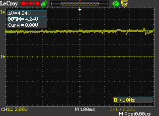
Stock frequency, ROG Realbench load current = ~45W
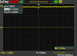
Stock frequency, Prime95 load current =~76W
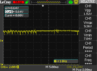
5GHz CPU frequency, ROG Realbench load current = ~93W
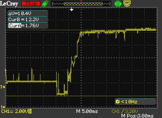
5GHz CPU frequency, Prime 95 load current=~131W
With the data acquired, we can identify where our “self-imposed” limits lie. We will add our obligatory disclaimer at this point and state that overclocking has risks and voids warranty unless you opt for Intel’s Performance Tuning Protection Plan. Keep that in mind, as there’s no way for us to guarantee things won’t go awry if you overclock a CPU. All risks are your own. What follows is nothing more than a set of guidelines based upon our own experience.
In order run Prime95 at 5GHz, our CPU sample requires 1.35Vcore. Power consumption under that load comes in at 131 Watts, which is comfortably below 2X the stock power consumption of Prime95. I must confess, CPUs are usually power rated by application power rather than Prime95, hence leaving some headroom below the 2X figure is prudent.
So, if you’re running Prime95 as a short-term stress test, we advise using no more than 1.35Vcore with a 7700K CPU. If the CPU has not been de-lidded/re-lidded for a thermal paste upgrade, you’re likely to run out of thermal headroom around that voltage anyway.
Now, if you happen to be the type of user that spends more time running Prime95 than using a PC for other tasks, then we advise you reduce the maximum Vcore. "By how much?", you ask. Well, you’re on your own for that. Remember, it’s current that degrades or kills a CPU. Be mindful of how much load you’re placing on the chip long-term and act accordingly. There’s nothing worse than pushing insane levels of current through the die and then moaning when there’s degradation.
Realbench is far kinder to the silicon from a power consumption point of view. At 5GHz and 1.35 Vcore, the power drawn is only 93 Watts. The risk of degradation is far lower than when subjecting the CPU to the brutality of AVX-enabled versions of Prime95. In fact, you could push up to 1.40Vcore with Realbench, and still keep consumption below the power levels drawn by Prime95 at 1.35 Vcore, but that's as far as we'd go for sustained exposure to such workloads.
Immediately apparent from this data is the fact that Kaby Lake is very power efficient. Sub-150-Watt power consumption when dealing with the nasty loads of Prime95 at 5GHz is incredible. Even if you were to find a gem Skylake CPU capable of operating at the same frequency, power levels would be up around the 200 Watt mark to obtain stability. The upshot is that Kaby Lake's efficiency takes the focus off motherboard power delivery to a reasonable extent. Any motherboard costing more than $150 should be capable of overclocking these CPUs to the limits when using air or water cooling. That includes all the ASUS motherboards in our Z270 guide.
With the power side of things dealt with, we can take at whether the Kaby Lake architecture responds to lower temperatures when overclocking.
| CPU core frequency | Cooling | Vcore | Peak CPU temperature in Celsius | Realbench - 2 Hours Pass? |
|---|---|---|---|---|
| 5GHz | Dual radiator AIO (water temp 28C) | 1.28V | 70C | No |
| 5GHz | Triple radiator custom loop in temp controlled room. Water temp 18C | 1.28V | 63C | Yes |
| 5GHz | Noctua NH-D15 | 1.28V | 73C | No |
| 5GHz | Dual radiator AIO | 1.32V | 72C | Yes |
| 5GHz | Air - Noctua NH-D15 | 1.32V | 78C | Yes |
From an overclocking perspective, the only advantage a dual radiator AIO cooler has over the Noctua NH-D15 heatsink is lower CPU temperatures. Unfortunately for us, the temperature drop isn’t significant enough to reduce Vcore requirements. To obtain a Vcore advantage, our CPU sample requires its load temps are kept under 65 Celsius, which requires a water chiller holding the coolant temps to 18 Celsius, or an ambient room temperature of 13~15 Celsius with a custom water loop and 3 X 120MM radiator. Not exactly a mainstream scenario. Of course, there is variance between samples, so our results may not be reflective of all CPUs.
De-lidding the CPU’s IHS (integrated heat spreader), replacing the thermal paste with something more thermally conductive, and then re-lidding, can yield benefits. We’ve seen temperature drops between 13~25 Celsius when the procedure is performed correctly.
If you’re wondering why Intel uses paste that’s less thermally efficient than the exotic mixes available to consumers, consider all the thermal cycling a CPU is subjected to over a few years. Heat can cause thermal pastes to fracture, creep, or pump out over time, leading to hot-spots on the die. Intel’s choices are likely based on long-term evaluations and ease of mass-application on the production line. With that in mind, if you do happen to embark on the de-lidding journey, it’s probably wise to re-apply the paste periodically, especially if you’re using the CPU in a vertically installed motherboard.
The process of de-lidding is made easy due to the availability of tools such as the Delid-Die-Mate 2, designed by Roman Hartung (AKA Der8auer), and the Rockit 88 de-lidding tool. Both are simple to use, so choose whichever is available to you. The old fashioned method of using a razor blade to cut through the sealant is riddled with potential for failure, as it’s easy to damage the PCB, resulting in a partially-working or dead CPU – something we have experienced first hand.

The Delid Die Mate 2 - makes de-lidding easy
For our de-lidding expedition, we used Thermal Grizzly Conductonaut between the IHS and CPU, and also between the IHS and water block. Conductonaut is a liquid metal compound with excellent thermal conductivity – better than any other compound we’ve used to date. The application resulted in a 13~15 Celsius drop in core temperatures, leading to improved overclocking stability at lower voltages:
| CPU core frequency | Cooling | Vcore | Peak CPU temperature in Celsius | Realbench - 2 Hours Pass? |
|---|---|---|---|---|
| 5GHz | Dual Radiator AIO (water temp 28C) | 1.28V | 55C | Yes |
| 5GHz | Noctua NH-D15 | 1.28V | 62C | Yes |
Previously, the dual-radiator AIO setup wasn’t stable at 5GHz with anything less than 1.328V. The re-pasting adventure provided temp drops that are substantial enough to reduce required Vcore to 1.28V, which is in line with the previous result with water temps at 18 Celsius. The additional headroom also allows us to push the CPU 100MHz higher with a mere 16mv voltage hike (1.344 Vcore). Prior to de-lidding, the CPU required 1.38Vcore for the same frequency. The gains are real. Just bear in mind that it will void Intel’s warranty. Interestingly, we have heard that some retailers are selling re-pasted CPUs and providing their own warranty (Case King and OCUK). It may be a worthwhile option if fiddly DIY doesn't sit well with you.
Memory frequency expectations
From everything we have seen to date, Kaby Lake’s overclocking prowess also applies to the memory side of the bus. Speeds of up to DDR-4133 are possible with four memory modules on our ROG Maximus series boards, while the Maximus IX Apex and Strix Z270I Gaming models manage DDR4-4266 thank to their optimized two-slot design.
As always, we’re going to recommend being conservative and opting for memory kits rated below DDR4-3600 if you favour plug-and-play. Above those speeds, manual tuning can be required due to variance between CPUs and other aspects of the system. Leave faster kits to enthusiasts who like to spend their time tweaking the system.
Also of merit for plug-and-play aspirants: be sure not to combine memory kits. Purchase a single kit rated at the memory frequency and density you wish to run. When combining memory kits – even of the same make and model – there’s no guarantee that the kits will run at the rated timings and frequency of a single kit. In cases where such configurations do not work, a lot of manual tuning is required, which isn’t for those of us who are light on experience and short on time.
For the enthusiasts out there, right now, all the latest high-speed memory kits are using the famous Samsung B-die ICs. It’s good stuff. Should temptation get the better of you and you’ve got your sights set on a DDR4-4000+ kit, be sure to provide adequate airflow over the memory modules. Good B-die based modules are sensitive to temperature, which can affect their stability. A capable memory cooler pays dividends if you intend to push the memory hard.

GSkill's DDR4-4266 TridentZ memory kit - 16GB of Samsung B-Die goodness....
Outside that, be mindful that some CPUs don’t like running high memory speeds when nearing the upper-end of their overclocking potential. In such cases, reducing the memory frequency by a ratio or two can help stabilize CPU core frequency without requiring additional Vcore.
Also noteworthy is that the highest working memory ratio is DDR4-4133. Higher speeds require adjustment of BCLK with the DDR4-4133 (or lower) ratio selected. If you do purchase a memory kit rated faster than DDR4-4133, don’t be alarmed if you see BCLK being changed to a higher value when you select XMP. The change is mandatory.
Uncore frequency
Uncore frequency – AKA Cache frequency in the ASUS firmware – can also be overclocked. The actual gains from overclocking the Uncore are application dependent, as it affects L3 cache access times. Generally, we prefer to focus on CPU frequency first, followed by memory frequency, and then we experiment with Uncore frequency.
Voltage wise, the Uncore shares the CPU Vcore rail. As a result, when we increase Vcore, we’re also increasing the Uncore voltage. That’s why there is some sense in overclocking the Uncore; you might as well claim the overclocking margin there is on the table, as you’ll be increasing voltage to the Uncore domain when you overclock the CPU.
From a frequency perspective, good CPU samples are capable of keeping Uncore frequency within 300MHz of the CPU core frequency when the processor is overclocked to the limits using air and water cooling. However, there may be a trade-off for the Uncore versus memory frequency on some CPU samples. If pushing memory frequency beyond DDR4-3800, it may be difficult to obtain stability with a Uncore frequency over 4.7GHz when the CPU cores are overclocked past 5GHz.
Typically, when Vcore is at 1.35V, Uncore frequencies between 4.7~4.9GHz are possible depending upon the quality of the CPU sample. As mentioned in the previous paragraph, CPU core and memory frequency affect how far the Uncore will overclock at a given level of voltage.
AVX offset
The AVX offset parameter allows us to define a separate CPU core multiplier ratio for applications that use AVX code. When AVX code is detected, the CPU Core multiplier ratio will downclock by the user-defined value. This feature is useful because AVX workloads generate more heat within the processor and they require more core voltage to be stable. Ordinarily, an overclock would be constrained by the hottest, most stressful application we run on the system. By using AVX offset, we can run non-AVX workloads, which don’t consume as much power, at a higher CPU frequency than AVX applications.
As an example, that means we can apply 50X ratio with a BCLK of 100MHz, resulting in a 5GHz overclock for non-AVX applications. We can then set the AVX offset parameter to a value 2 (or lower if required), which will reduce the CPU core ratio to 48X (4.8GHz) when an AVX workload is detected. This ensures the system stays within its thermal envelope, without our overclock being constrained solely by the AVX workload.
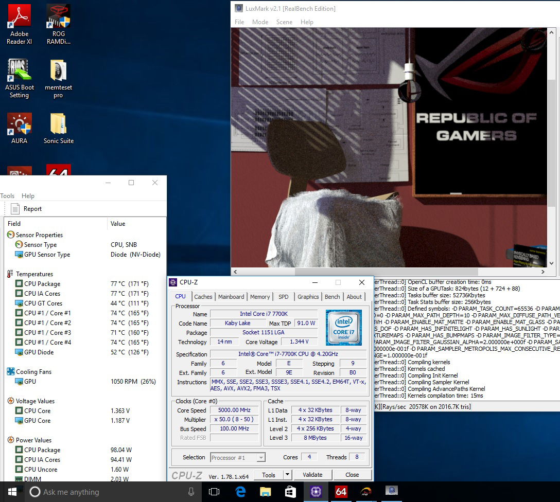
5GHz overclock maintained during non-AVX workloads
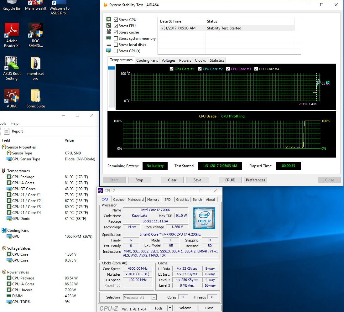
And downclocked to 4.8GHz during AVX workloads (AVX offset = 2)
For the most part, AVX offset works well in practice. The only caveat we have experienced is that we cannot apply a separate Vcore for the AVX ratio. Being able to define the amount of Vcore applied would help us to tune each CPU sample to the optimal voltage for AVX workloads. Crude workarounds for this limitation include using Offset Mode for Vcore to reduce the voltage, or by manipulating load-line calibration, which affects how much the voltage (Vcore) sags under load. Both of these workarounds have implications for stability, so cannot be employed in all cases. The option to manually set a core voltage for the AVX Offset ratio would be advantageous. We have already spoken to Intel about this and made suggestions for future iterations of AVX offset. The changes required are significant, so we likely won’t see them for a few generations; ergo, don’t expect them for Kaby Lake.
The other issue with AVX offset is that it only detects AVX workloads. There are applications and even some games that are multi-threaded, generating higher thermal loads than applications that aren't as intensive. In such cases, overclocking headroom is more thermally constrained than it should be. Fortunately, there's an exclusive ASUS workaround for the issue, and it's called CPU overclocking temperature control...
ASUS CPU overclocking temperature control
First unveiled on the X99 platform back in June 2016, the ASUS Thermal Control utility makes its way to the Z270 platform. This time, instead of being software based, it’s coded directly into the UEFI, and gets a name change to CPU overclocking temperature control:
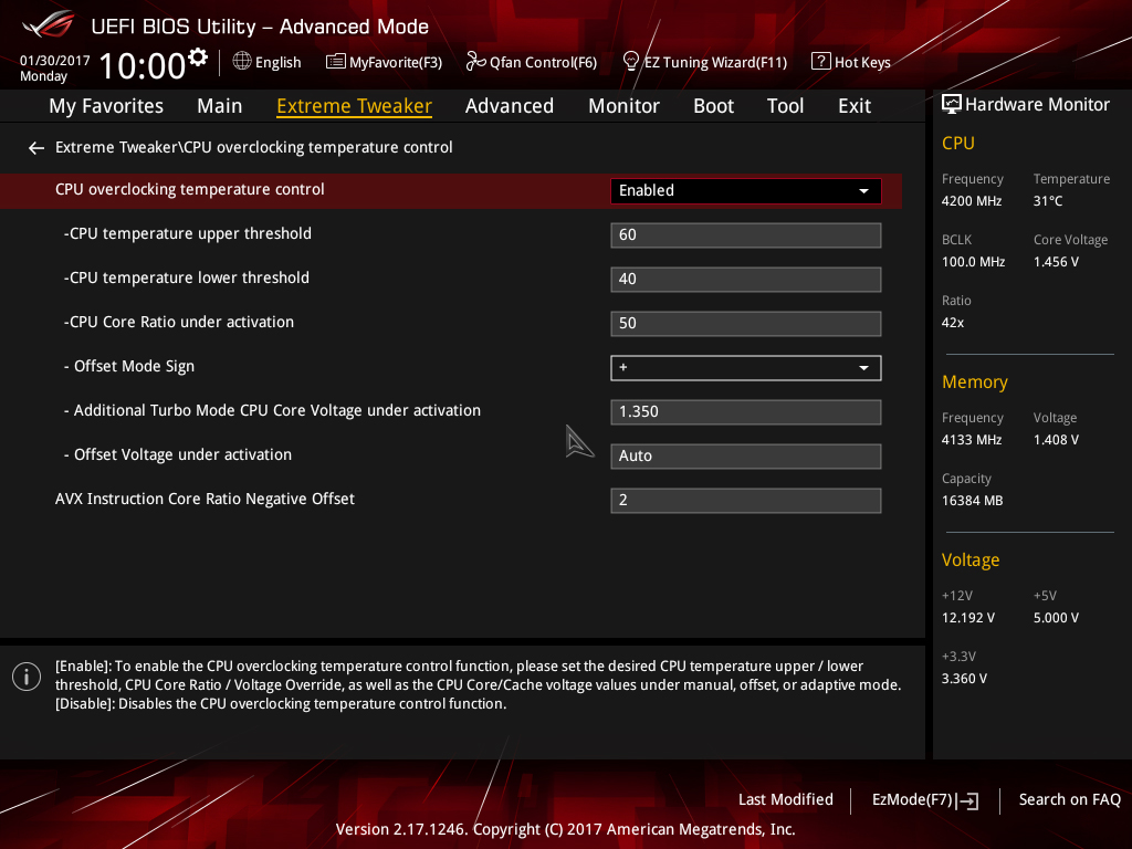
The temperature control options allow us to configure two CPU core frequency targets directly from firmware; one for light-load applications, such as games, the other, for more stringent workloads. Both overclock targets can be assigned separate voltage levels and temperature targets so that we can run games and light-load applications at higher frequencies than workloads that generate more heat. The feature works by monitoring temperature and then applying user-configured voltages and multiplier ratios when the defined thermal thresholds are breached.
Unlike AVX offset, the temperature control mechanism isn’t limited solely to AVX workloads. Any application that generates sufficient heat to breach the user-defined temperature threshold will result in the operating frequency and voltage being lowered to the user-applied values. In essence, this provides more flexibility than the AVX offset parameter and deals with some of its drawbacks.
Depending upon the cooling used, an extra 100~300MHz of overclocking headroom can be cajoled from a CPU with the ASUS temperature control features. It’s a handy tool for enthusiasts who want to wring out every MHz of headroom from the system.
Overclocking workflow
It’s time to lay out some overclocking methodology. Our approach to overclocking isolates portions of the system by using stress tests that focus on specific areas. Once the system is stable in all tests, we proceed to test all areas simultaneously. By doing things this way we avoid confusion, as isolating portions of the system while applying an overclock gives us fewer variables to debug when faced with instability.
Don’t worry if the references to adjustments don’t make sense right now. We’ll provide you with some screenshots of what to adjust on the following page.
- Before you overclock the system, run a stress test at stock settings - a one-hour test should suffice. Check that CPU temps under full load have sufficient headroom for overclocking, and that the system is stable. Keep a close eye on temps once the CPU is under full load for a few minutes, just to make sure it isn't throttling its frequency due to over-temperature (typically, 95 Celsius). CPU-Z and third-party tools such as AIDA are useful for monitoring frequency and temperatures. If there are any problems with temperatures or stability, do not proceed until you've found and fixed the issue.
- Assuming everything is okay, overclock the CPU cores first and establish stability before configuring the memory or cache ratios. We recommend using Adaptive voltage mode rather than Manual or Offset mode. Choose a CPU-intensive stress test. We prefer using a looped 1080p Handbrake encode (1~4 hours), as that's the toughest load we'll place on our system. Check CPU core temps once again to gauge how much headroom the cooling has for further overclocking. If the CPU is stable, increase the processor core ratios one step at a time while monitoring temps and noting the amount of Vcore required for stability.
- If you keep notes on the Vcore required for each multiplier ratio increase, you will find a certain point where the required Vcore increases exponentially. If your target usage scenario involves heavy multi-threaded workloads, then it is wise to set the overclock frequency at a point before there is an exponential rise in the required voltage for stability. Setting the overclock using this method results in lower power consumption and is kinder to the CPU from a longevity point of view.The absolute max temperature we’d like to see during our usage case would be 80 Celsius during a Handbrake encode, which provides us with some headroom for the few summer days we experience here in the UK. The gist is to ensure temperatures under full load have sufficient margin to account for ambient variance due to weather or sources of heat within a PC case – catering for such variance helps avoid throttling.
- Once CPU core stability is established, configure XMP for the memory modules - if they support XMP - and run a memory-intensive stress test to ensure the system is stable. (Recommended stress tests are listed later in this guide.) If stability cannot be established with XMP engaged, try reducing the CPU core clock to debug where the issue lies. Keep Vcore at the same value when doing this, just to remove CPU core instability from the equation. If the system becomes stable at a lower operating frequency, then you may need to tune Vcore, System Agent (VCCSA), and VCCIO voltages. If none of these help stability, the memory timings or DRAM voltage may need adjustment.
- If the system is stable, you may wish to experiment with Uncore overclocking. 500% of coverage in the HCI Memtest is a good test for the Uncore, as is AIDA64’s Cache test. Keep a close eye on temps to ensure they do not exceed 80 Celsius.
- If you’ve made it this far, consider optimizing the overclock by using the ASUS temperature control features and AVX offset for light and heavy workloads.
Preferred Stress Tests
Here are our preferred choices for stress testing the Kaby Lake architecture:
- ROG Realbench for all round application stability. Use the stress test option with the correct amount of system memory assigned. Run for 2~8 hours. The stress test uses a combination of Handbrake, Luxmark and Winrar to test multiple areas of the system. It works very well as a stress test for this platform.
- Google Stressapp Test via Linux Mint (or another compatible Linux disti) is the best memory stress test available. Google use this stress test to evaluate memory stability of their servers – nothing more needs to be said about how valid that makes this as a stress test tool.Install Linux Mint from here: http://www.linuxmint.com/download.php
Install the Google Stress App test from here: http://community.linuxmint.com/software/view/stressapptestOnce installed open “Terminal” and type the following:stressapptest -W -s 3600This will run stressapp for one hour. The test will log any errors as it runs. Stressapp is more stringent than Memtest for DOS, HCI Memtest for Windows, and any other memory test we have used for isolating the memory bus.
- HCI Memtest– A good memory and Uncore stability test. Run as many instances as there are logical CPU cores, assign 90% of the available memory, and run until 500% coverage is completed (longer if preferred).
- AIDA64 – Includes a variety of stress test options to load various parts of the system. We recommend the Cache test for evaluating stability of the Uncore. Run for 2~8 hours.
UEFI setup for overclocking
We've taken the time to walk you through UEFI setup for overclocking, below. If you're confused or stuck after reading through this section of the guide, head over to the overclocking section of the ROG Forums and ask questions. We'll help!
1) If using water-cooling with a dual or triple radiator, set an adaptive Vcore of 1.30V and a CPU core ratio of 49X. When using good air cooling, set a core ratio of 48X with a Vcore of 1.25V:
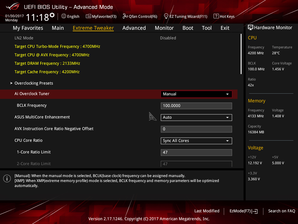
- Enter UEFI by pressing delete during POST.
- Navigate to the Extreme Tweaker menu (Ai Tweaker on non-ROG motherboards)
- Set Ai Overclock Tuner to Manual
- Set CPU Core Ratio to Sync All Cores
- Enter a value of 49 or 48 in the 1-Core Ratio limit box (according to the CPU cooling used)
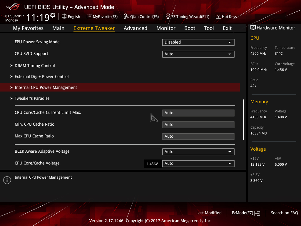
Navigate to Internal CPU Power Management and press enter
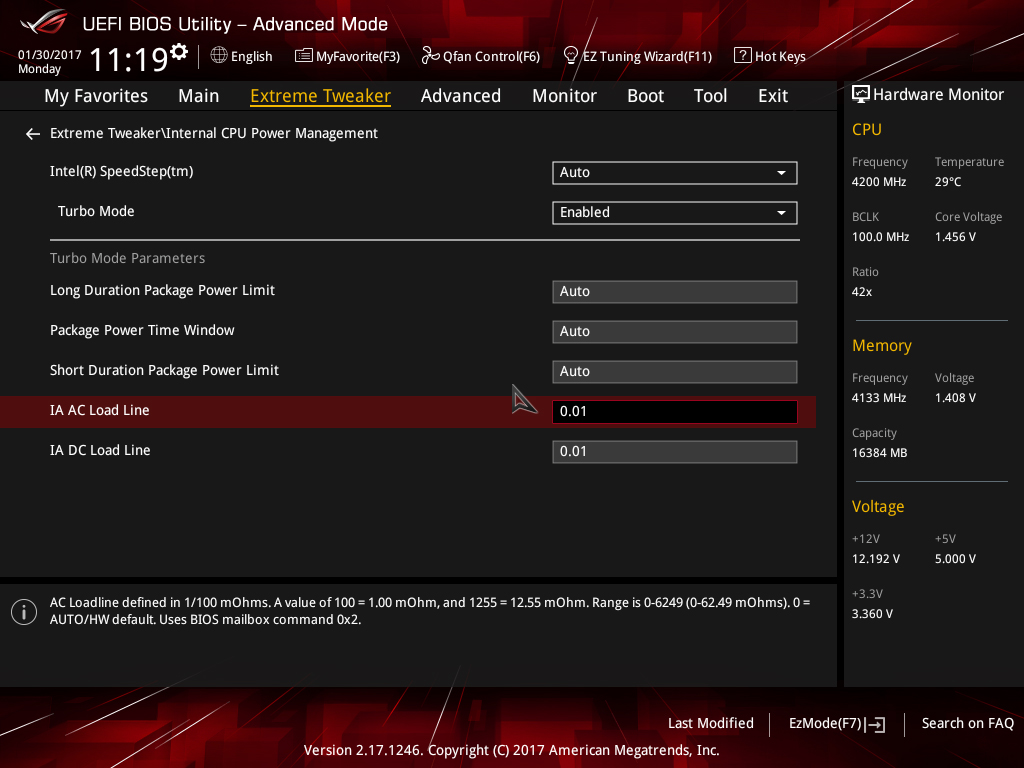
- Set IA DC Load Line to 0.01
- Set IA AC Load Line to 0.01
- Press the escape key on your keyboard to return to the previous page
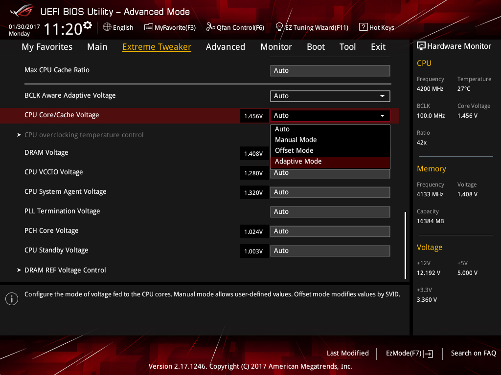
Scroll down to CPU/Cache Voltage (CPU Vcore) and select Adaptive Mode
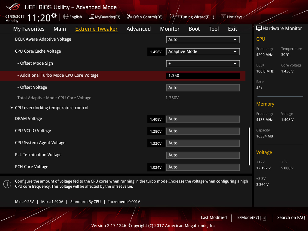
- Enter a value of 1.30 in the Additional Turbo Mode CPU Core Voltage box if you are using water cooling.
- Enter a value of 1.25V if you are using a good air cooler such as the Noctua NH-D15S
- Press F10 to save and exit UEFI
2) Check if the system will POST and enter the OS. Once in the OS, run your preferred stress test.
3) If the system is not stable, leave Vcore at the previous value and reduce the CPU core ratio by one, then repeat step 2.
4) If the system is stable, try increasing the core ratio by one step while using the same level of Vcore and repeat step 2. If not stable at the higher ratio, check load temperatures and if they are acceptable under full stress test load, increase Vcore by 0.02V, then repeat step 2.
If running the AVX2 versions of Prime 95 we recommend using a maximum Vcore of 1.35V with triple-radiator cooling. If using less capable cooling, reduce the voltage according to temperatures. Keeping full-load temps below 80 Celsius is advised.
5) If the system is stable, you may enable XMP for the memory and re-gauge stability.
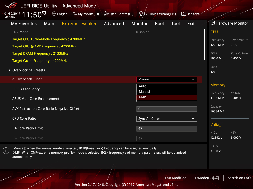
To enable XMP for your memory modules (assuming they support XMP), set Ai Overclock Tuner to XMP and press enter
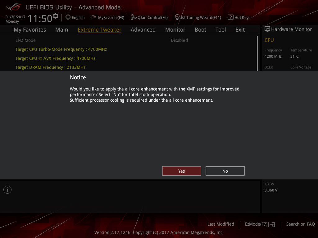
- When prompted to enable all core enhancement, press enter to confirm. It doesn’t matter if you select yes or no for this as we’re overclocking the CPU and this setting is inactive when the CPU is overclocked.
- Save and exit UEFI by pressing F10
6) If enabling XMP causes instability, then tuning of System Agent and CPU VCCIO voltage may be necessary.
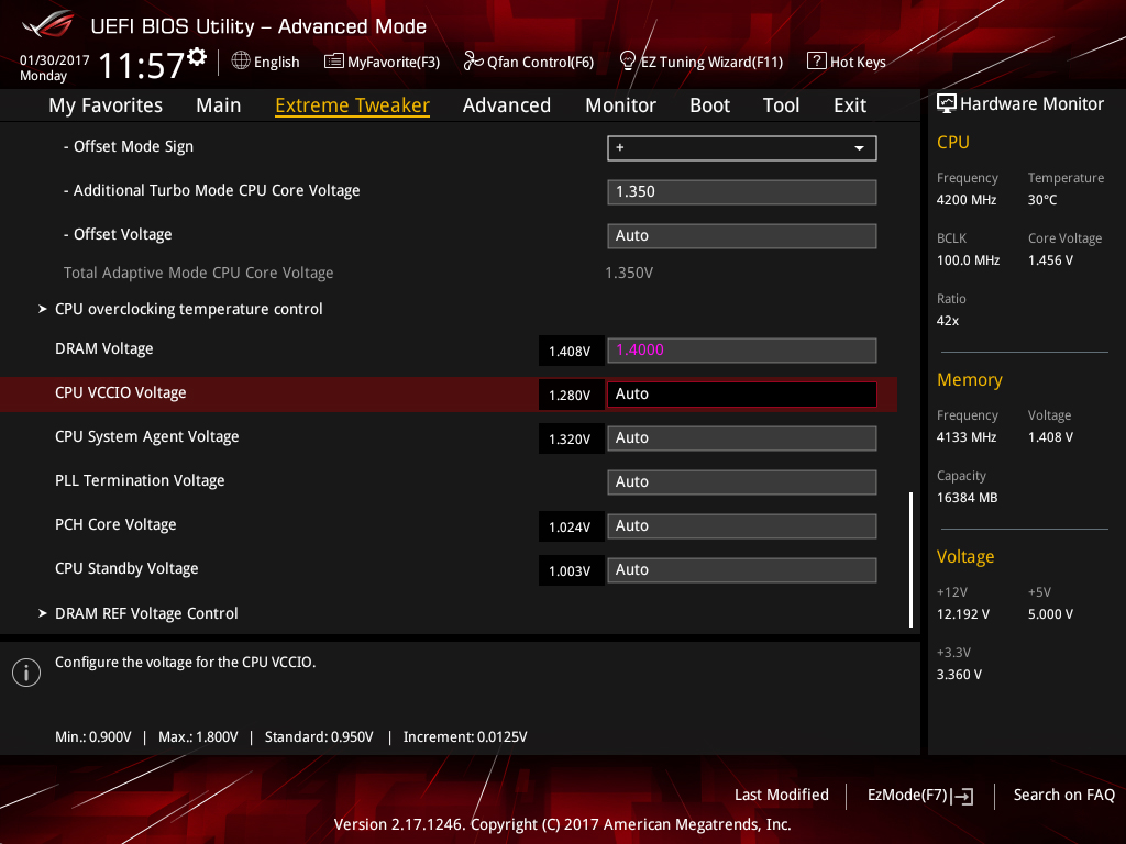
CPU VCCIO and CPU System Agent voltages are found in the Extreme Tweaker page (scroll down to the bottom of the page to find them). These two voltages are sensitive to changes because they are related to signaling. Applying too much voltage can cause instability. Note the auto value being used by the motherboard (displayed to the left of the entry box) and apply gradual changes either above or below that value.
| DDR4 frequency range | Required CPU VCCIO Voltage range | Required CPU System Agent Voltage range |
|---|---|---|
| DDR4-2133 ~ DDR4-2800 | 1.05V ~ 1.15V | 1.05V ~ 1.15V |
| DDR4-2800 ~ DDR4-3600 | 1.10V~1.25V | 1.10V~1.30V |
| DDR4-3600 ~ DDR4-4266 | 1.15V~1.30V | 1.20V~1.35V |
The values shown in the table above are a guideline only. Some CPUs may require more voltage and others less. The amount of voltage required depends on the capabilities of the CPU's memory controller and the memory kit used. We've seen some samples that can achieve DDR4-4000+ speeds needing no more than 1.25V for System Agent voltage. In fact, using more voltage simply makes them unstable. Bear that in mind.
Apply changes, then retest for stability. Also be sure to check the system can POST consistently from a power cycle and warm restart. Memory training occurs during these periods, and if these voltages haven't been tuned properly, it will result in the system being unable to POST or BOOT.
7) Assuming all is well, you can experiment with Uncore overclocking if you wish:
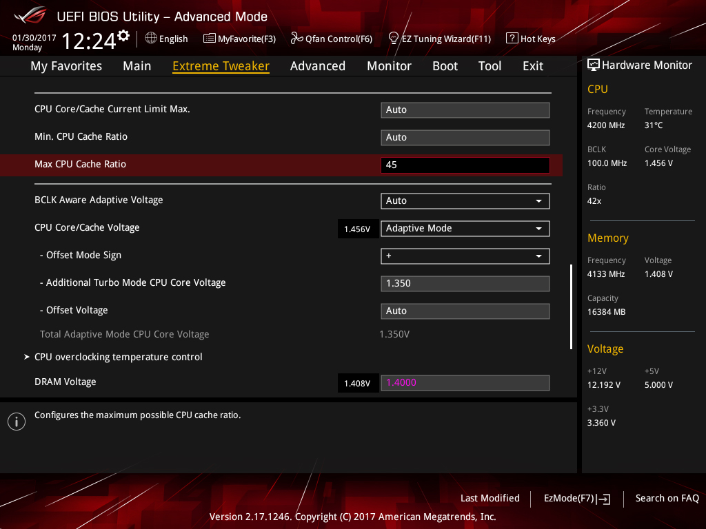
To configure the Uncore ratio, enter the required value in the Max CPU Cache Ratio box. For 4.5GHz, you’d select a value of 45 (assuming BCLK is at 100 MHz). We recommend starting at 45 and working your way up. Note, stability with an Uncore frequency of 4.5GHz is dependent on how much CPU Core/Cache voltage you have applied and is affected by memory frequency.
Use the same method to overclock the Uncore as you did with the CPU cores. However, we do not recommend increasing CPU Core/Cache voltage just to stabilize a higher Uncore frequency. For normal use and most workloads, the performance increase is negligible. Take whatever you can get for free at the same CPU Core/Cache Voltage level you applied to stabilize the CPU cores.
You can run AIDA64’s Cache stress test to check if the applied Uncore overclock is stable. Adjust the Uncore frequency as necessary to achieve stability.
8) If you’d like to make use of the AVX Core Ratio Negative Offset to reduce the CPU Core frequency under AVX workloads, navigate to the setting in UEFI and simply apply the required value in the box:
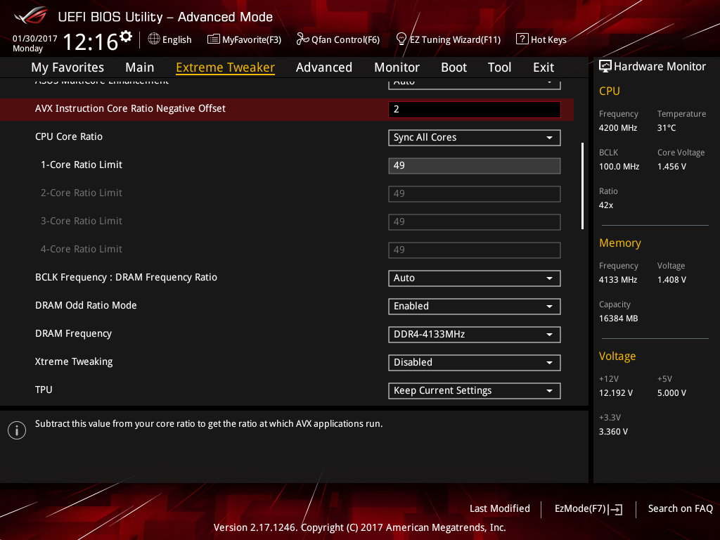
In this case, we’ve applied an AVX offset of 2, and as or Core Ratio limit is set to 49, this results in a CPU core frequency of 4.7GHz when an AVX workload is run on the system. You can test the applied setting by running an AVX application within the operating system and seeing how the system responds. If instability is encountered, you may need to increase the CPU core voltage by a small amount.
As an alternative to using an AVX offset, consider using the ASUS CPU overclocking temperature control feature to maximize the CPU overclock.
ASUS CPU overclocking temperature control guide
The CPU overclocking temperature control utility should only be used once you have established a stable overclock for the heavy-load applications you wish to run on the system. With that out of the way, you can determine the stable light-load frequency. Obviously, you’ll need to understand how to use the temperature control utility first. We provide a description of each function below.
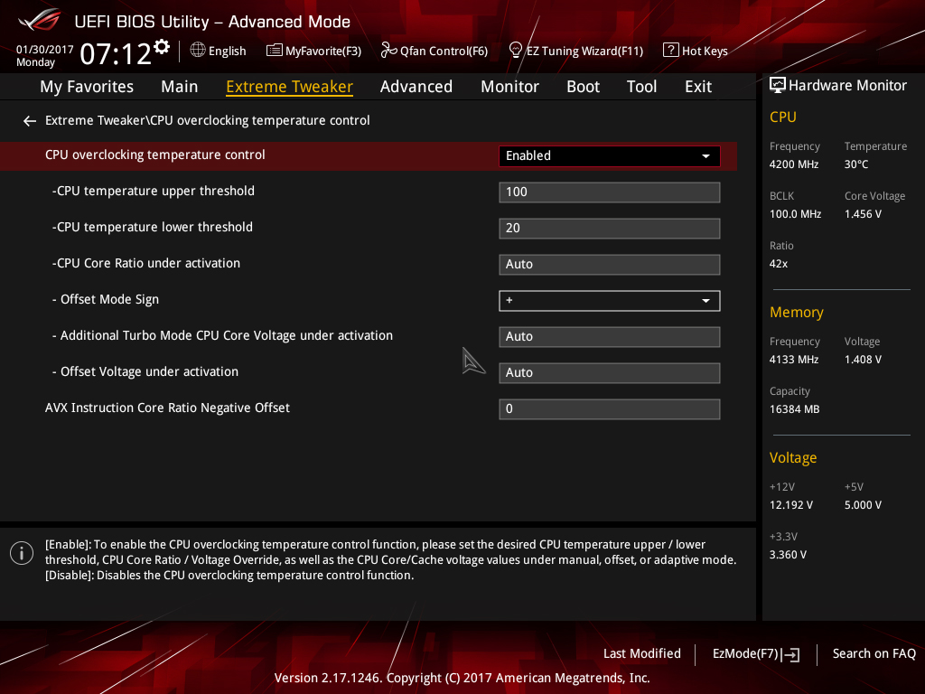
CPU overclocking temperature control: Allows you to enable or disable the temperature control features.
CPU temperature upper threshold: This defines the high-temperature threshold. When the CPU package temperature exceeds this value, the multiplier ratio and voltage will change to the values defined in the CPU Core Ratio under activation, Additional Turbo Mode CPU Core Voltage under activation, and Offset Voltage under activation boxes.
CPU temperature lower threshold: Defines the low-temperature threshold. When the CPU package temperature is below this value, the core ratio and voltage will return to the overclock frequency applied in the Ai Tweaker/Extreme Tweaker menu (light-load frequency).
CPU Core Ratio Under activation: Defines the core ratio that is applied when the temperature breaches the Upper Temp Limit setting.
Offset Mode Sign: Configures whether the value entered in the Offset Voltage under activation is subtracted from or added to the Additional Turbo Mode CPU Core Voltage under activation value. A setting of “+” will add the applied voltage, while a setting of “-“ will subtract it. The Offset Mode Sign parameter is only available when using Adaptive Mode for CPU core voltage.
Additional Turbo Mode CPU Core Voltage under activation: Sets the target voltage (Vcore) for the throttle ratio. Configure UEFI to Adaptive Mode for Vcore to use this option. The applied voltage needs to be sufficient for the throttle ratio. To use this parameter, enter the value you wish to apply when the CPU is faced with a heavy load. So, if you want to use 1.35V, enter 1.35 into the box. The function is only available when using Adaptive Mode for CPU core voltage.
When using Manual Mode for CPU core voltage, this setting becomes “CPU Core Voltage Override under activation.” The method of applying voltage is identical to using Adaptive Mode.
Offset Voltage under activation: Allows setting an offset voltage to Vcore for the throttle ratio. This setting works in conjunction with Additional Turbo Mode CPU Core Voltage under activation to change Vcore to the target value. For most users, this setting can be left at the default unless you need to use an offset to lower the voltage below the minimum adaptive voltage for the applied CPU ratio.
Note: The CPU Package temp is utilized by the ASUS Thermal Control tool because it represents the average core temperature reported by the internal thermal sensors over a 256-ms period – this makes it a perfect choice for the task.
Making use of ASUS CPU overclocking temperature control
In order to make use of the temperature control features effectively, we need to make a two-point evaluation:
- Testing with games/light-load applications at the upper CPU frequency
- Using the Thermal Control Tool with an all-core test – ROG RealBench stress test recommended.
In our case, the CPU is Realbench stress test stable at 5GHz with 1.35 Vcore. With that in mind, it should be possible for us to run light-load applications at 5.1GHz using the temperature control function.
Tuning Vcore for the light-load frequency can take some time. When a heavy-load application is run, there is a momentary delay before the clock frequency drops to the throttle target. That is because temperature changes lag behind the execution of a workload. Vcore needs to be sufficient to handle the momentary load before the clock frequency drops to the throttle target. You will need to bear this in mind when tuning – be prepared to provide some headroom for Vcore! We recommend using the application you intend to run at the throttle frequency. The heaviest load we recommend for this portion of testing is Handbrake with a maximum of 1.43Vcore at the upper frequency. This will avoid excessive current draw before the clock speed is lowered to the applied throttle frequency and voltage.
We also need to be mindful when setting the CPU temperature upper threshold. If set too high, the CPU remains at the light-load frequency for too long; this can result in instability unless we provide sufficient Vcore to handle a heavy workload. The temperature control mechanism needs adequate time to react and lower the CPU frequency to our chosen throttle point.
For frequencies above 5GHz, we have found that values under 65 Celsius are best because higher temperature thresholds need more Vcore. It is better still if one sets the threshold closer to the peak temperature that the “most intensive” light load generates. That said, if using good cooling for the CPU, you should not see temperatures over 60 Celsius during light loads, anyway.
To make things easier for you, we’ve included a sample screenshot of our temperature control settings for a 5.1GHz overclock that drops to 5GHz under heavy loads and to 4.9GHz under AVX workloads.
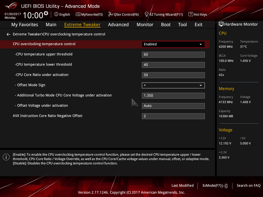
When the CPU temperature exceeds 60 Celsius, the CPU Core ratio will change to 50, which gives us 5GHz. The CPU Vcore will also be reduced down to 1.35V. The core ratios and core voltage will remain at these values until the CPU temperature falls below 40 Celsius. Once it falls below that temperature, the CPU core ratio will return to its original value; in our case that’s 52X (configured in the Extreme Tweaker page).
UEFI rundown
The Extreme Tweaker (Ai Tweaker) section in the UEFI’s Advanced Mode is our area of focus for the final portion of this article. We’ll pick out functions of interest, or those that often raise questions, and provide some insight about what they do and when to use them. It’s a valuable resource if you’d like to improve your knowledge past the elementary levels. Don’t worry if it all doesn’t make sense, as not all of it needs to.
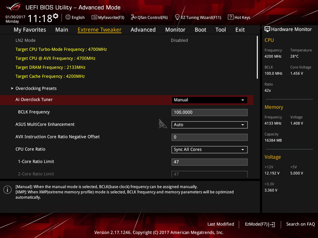
Ai Overclock Tuner: Set to Manual if you wish to adjust BCLK manually and other overclocking settings manually. Use the XMP setting to apply the Extreme Memory Profile of compatible memory modules.
BCLK Frequency: BCLK is the reference clock supplied to the CPU, Uncore, memory, PCIe, and DMI buses. Hence, any changes to BCLK will affect the operating frequency and stability of all associated domains. Ordinarily, changes to BCLK should not be required for a system that will be used as a workstation or gaming rig. The only exceptions to that rule are when a DRAM ratio that requires a different CPU strap needs a slight BCLK offset to obtain the correct memory frequency.
To take the hassle out of calculating frequency changes as a result of BCLK adjustments, the target frequency for the CPU, CPU AVX offset, DRAM, and Cache (Uncore) is automatically calculated and shown at the top left of the Ai Tweaker page.
ASUS Multicore Enhancement: Setting to Auto applies the Turbo ratio to all cores. Setting to Disabled uses Intel Turbo policies. These options are only effective at stock CPU settings. When a manual overclock is applied, the Turbo ratios are assigned according to the CPU Core Ratio settings.
AVX Instruction Core Ratio Negative Offset: This setting reduces CPU core frequencies by the applied value when an AVX workload is run. The thermal output of AVX workloads is an order of magnitude higher than for non-AVX workloads, which is why this setting has been introduced. By using this feature, we can utilize a higher operating frequency for light-load applications while heavy-load applications that contain AVX code will downclock the processor to help keep core temperatures below the throttling point.
CPU Core Ratio: There are two options for core ratio control:
Sync all cores: All core ratios will be set to the same value.
Per Core: Allows ratios to be applied to each core independently. In this scenario, when non-threaded applications are run, they can be assigned to cores that are running at a higher frequency to improve performance. However, current versions of the Windows operating system are configured to balance loads across all available cores, which results in all available cores reverting to the same ratio as the slowest core when faced with a workload. The workaround is to assign processor affinity for non-threaded workloads manually via the Windows Task Manager.
We recommend using the Sync All Cores setting in association with the AVX Instruction Core ratio Negative Offset setting, or with the ASUS CPU overclocking temperature control features to get the best performance from the Kaby Lake architecture.
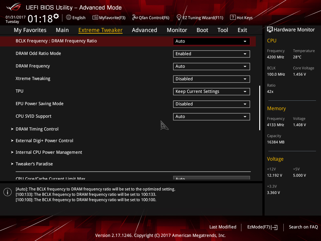
BCLK Frequency: DRAM Frequency Ratio: Sets the ratio of DRAM frequency to BCLK. For normal use, this setting can be left on Auto, as it will choose the best ratio according to the user-selected DRAM Frequency.
DRAM Odd Ratio Mode: When enabled, all DRAM ratios are made available – spaced at 100MHz and 133MHz intervals all the way to the functional DDR4-4133 ratio.
DRAM Frequency: Allows you to select the memory operating frequency. When XMP is configured, the correct frequency for the memory kit is selected automatically. The DRAM ratio option only needs to be set if you intend on setting the memory speed manually for overclocking purposes.
Note that the highest working memory ratio is DDR4-4133. Higher speeds require usage of BCLK with the DDR4-4133 (or a lower) memory ratio selected.
Xtreme Tweaking: When enabled, provides a score boost in very old legacy benchmarks such as 3D Mark 01. It has no impact on performance for other applications so can be left disabled.
CPU SVID Support: Can be left on Auto for all normal overclocking. SVID allows the processor to communicate with the CPU Core Voltage power delivery circuit in order to change voltage on-the-fly for power saving purposes and allows power levels to be read by monitoring software. For Adaptive and Offset Mode for CPU Core/Cache Voltage, this setting must be set to Auto or Enabled. For all normal overclocking a setting of Auto can be used without requiring adjustment.
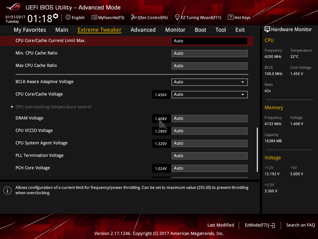
CPU Core/Cache Current Limit Max: Allows setting a current limit for frequency/power throttling. Can be left on Auto for all normal overclocking purposes to prevent inadvertent throttling when the CPU is under load.
Min. CPU Cache Ratio: Defines the minimum Uncore ratio when enters CPU power saving state. Can be left on Auto for all normal use unless you wish to experiment with a different minimum value. To prevent downclocking of the Uncore domain, set the minimum ratio to the same value as the maximum ratio.
Max CPU Cache Ratio: Defines the maximum Uncore ratio when the CPU enters load state. For overclocking purposes keeping the maximum value within 3 ratios (lower) of the applied CPU Core ratio is sufficient for performance. Note that changes to the maximum ratio should not be experimented with until stability has been established for the CPU cores and memory (DRAM).
CPU Core/Cache Voltage: Sets the voltage control mode for CPU Vcore and the Uncore:
Manual Mode: Allows setting of a single value for Vcore that is applied across all Core ratios, irrespective of application load.
Offset Mode: In Offset Mode, we can add or subtract voltage from the CPU’s default voltage for a given CPU core ratio. The default voltage scales according to the active multiplier ratio. This provides power saving when application loading is light. The side effect to using offset mode is that any offset value we select will be applied to all core ratios. This can result in too much or too little voltage being applied for a given ratio, which leads to instability.
If you wish to use Offset Mode, then bear in mind that the Vcore displayed in the UEFI is simply a snapshot of the offset voltage stack; the firmware interface only places a partial load on the CPU. The full-load voltage in the operating system will be different, so you will need to check the voltage by running a suitable application within the OS. Use Ai Suite to monitor the voltage when the system is under full load. Also, bear in mind that the default voltage receiving the offset changes with the applied CPU ratio.
Adaptive Mode: Adaptive Mode was developed to account for the inadequacies of Offset Mode for overclocking. We use it to specify the voltage used when the CPU is faced with a heavy application load. The voltage we set is the maximum voltage the PCU is allowed to apply, which takes all the load-related guesswork hampering Offset Mode out of the equation. The other boon of Adaptive Mode is that it does not alter voltages for non-Turbo CPU ratios, allowing us to enjoy the benefits of power saving without the voltage adjustment range issues presented by the Offset Mode function. We recommend Adaptive Mode for all normal overclocking.
To use Adaptive Mode, simply enter the full load voltage you wish to use in the Additional Turbo Mode CPU Core Voltage box. So, if you wish to set 1.20V for full load, just type 1.20 into the box. The target full-load voltage is shown in the Total Adaptive Mode CPU Core Voltage area.
When using Adaptive Mode, configure the following settings within the Internal CPU Power Management sub-section:
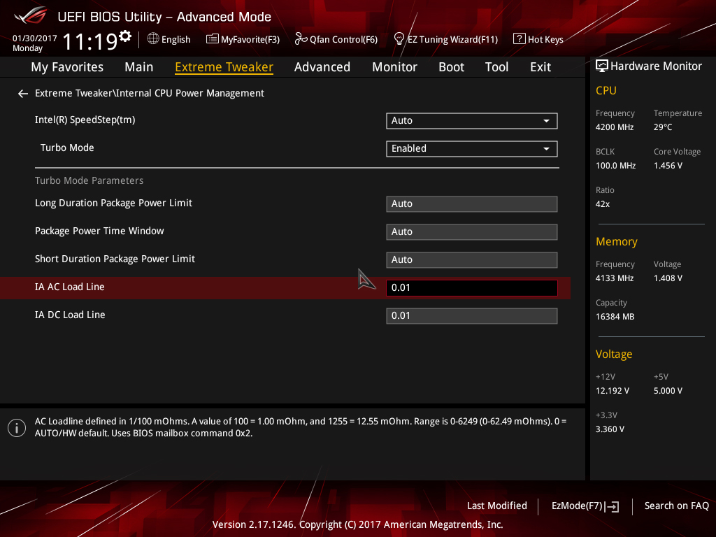
- Set IA AC Load Line to 0.01
- Set IA DC Load Line to 0.01
- Press the escape key on your keyboard to return to the previous page
Setting these values keeps the Adaptive Mode voltage closer to the user-applied value when the processor is under full load.
Note that the Adaptive voltage target works on the Turbo ratios only. So, if you use a non-Turbo CPU ratio, the value in the Adaptive voltage setting box will not be applied. In such instances, use Offset Mode or Manual Mode for CPU Core/Cache Voltage.
The major caveat of Adaptive Mode is that the minimum possible voltage for a given ratio is pre-programmed into the CPU. If you happen to have a very good CPU that can run at a lower voltage than the minimum adaptive voltage for a given ratio, there are only two ways to lower the value. The first method is to apply an offset. That’s why there is the option to apply an offset when in Adaptive mode. The offset value is added or subtracted from the Additional Turbo Mode CPU Core Voltage box, and the total is displayed in the Total Adaptive Mode CPU Core Voltage pane. The side effect of applying an offset is that it affects the entire voltage stack – from idle to Turbo ratios, which can limit the usable offset voltage range.The second method is to use the CPU Load-line Calibration setting in the External DIGI+ Power Control section. Using a lower value will lead to more sag under load, resulting in a lower voltage. Again, the issue with this is that it will affect how much voltage the CPU receives under all loading conditions, which can lead to instability when it is too low for a given load state, or when the CPU transitions from idle to load state.
Even with those caveats, we still recommend using Adaptive Mode for all normal overclocking, unless your processor can run at voltage levels that fall substantially below the minimum adaptive voltage for the applied CPU core ratio.
DRAM Voltage: Sets the memory voltage (VDIMM) for the memory modules. When XMP is applied for the memory kit, the correct voltage will automatically be configured. Adjustments are only necessary if your memory kit does not support XMP (unlikely), or if the memory is proving unstable after making adjustments to System Agent voltage, VCCIO, and memory timings.
CPU VCCIO Voltage: This rail is for the IO transceivers within the CPU. Its primary impact is on memory stability, although, it usually does not need to be increased as much as the System Agent voltage. Keeping this rail within ~0.05V (lower) of the System Agent voltage is often sufficient to stabilize memory frequency.
When making adjustments to this rail, bear in mind that applying too much voltage can lead to instability. Make adjustments gradually.
CPU System Agent: The System Agent is responsible for handling IO between the CPU and other domains. From an overclocking perspective, the System Agent voltage is especially important for memory overclocking.
For memory speeds over DDR4-3600 or if using high-density memory kits, voltages up to 1.35V may be required. Some CPUs have “weak” memory controllers that require elevated voltages to maintain stability. If possible, do not venture too far from 1.35V as a maximum.
The System Agent voltage can induce instability if set too high, so it is wise to make gradual changes rather than applying arbitrary values and hoping for the best.
PLL Termination Voltage: Leave this at Auto; adjustment of this voltage is only beneficial for extreme overclocking with sub-zero CPU cooling.
PCH Core Voltage: This is the core voltage supply for the PCH (platform controller hub). This setting should not need adjustment for most overclocking.
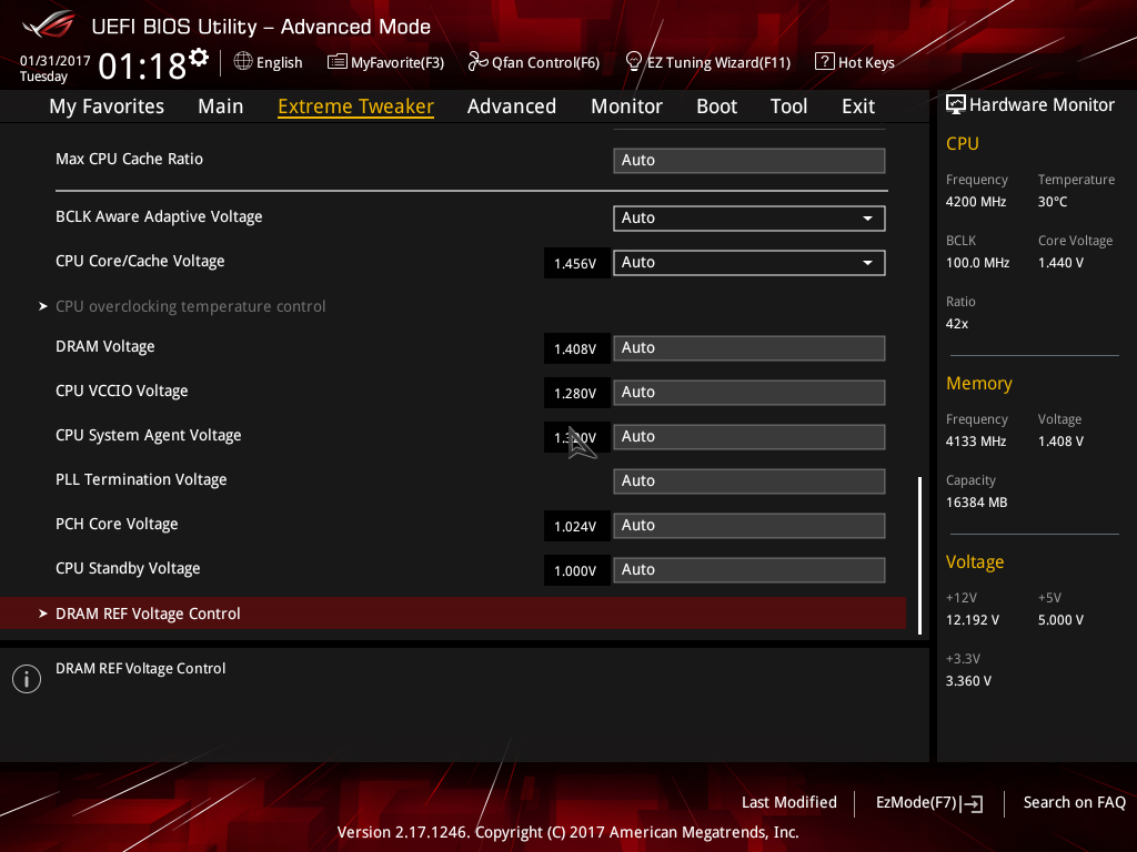
CPU Standby Voltage: Leave at Auto for all normal overclocking. Adjustment of this rail is only required for extreme overclocking with sub-zero cooling.
That concludes the Kaby Lake overclocking guide. We look forwards to your results! Please post any questions in the ROG Forums.
Author
Popular Posts
How to adjust your laptop's P-Cores and E-Cores for better performance and battery life
Introducing the ROG Astral GeForce RTX 5090 and 5080: a new frontier of gaming graphics

How to Cleanly Uninstall and Reinstall Armoury Crate
How to configure your PC's RGB lighting with Aura Sync
How to upgrade the SSD and reinstall Windows on your ROG Ally or Ally X
LATEST ARTICLES
See the mammoth ROG Dominus build that takes Intel's 28-core Xeon W-3175X to the Extreme
The ROG Dominus Extreme pushes the boundaries of PC performance in our awesome CES 2019 build.
Breaking world records with the ROG Maximus XI Gene and the Intel Core i9-9900K
Tasked with pushing performance on the Z390 platform as far as possible, we invited the best overclockers to ROG HQ for a week of extreme overclocking.
How to overclock your system using AI Overclocking
AI Overclocking one-click tuning makes its debut on Z390 motherboards and we have a quick how-to guide to get you started.

HW GURUS win the ROG OC Showdown Team Edition 2
The results are in from our second ROG OC Showdown Team Edition. See who posted the top scores.
Breaking records with the Maximus X Apex and i7-8700K
ROG is obsessed with chasing the highest overclocks and fastest performance, and Coffee Lake is our new muse on the Maximus X Apex.
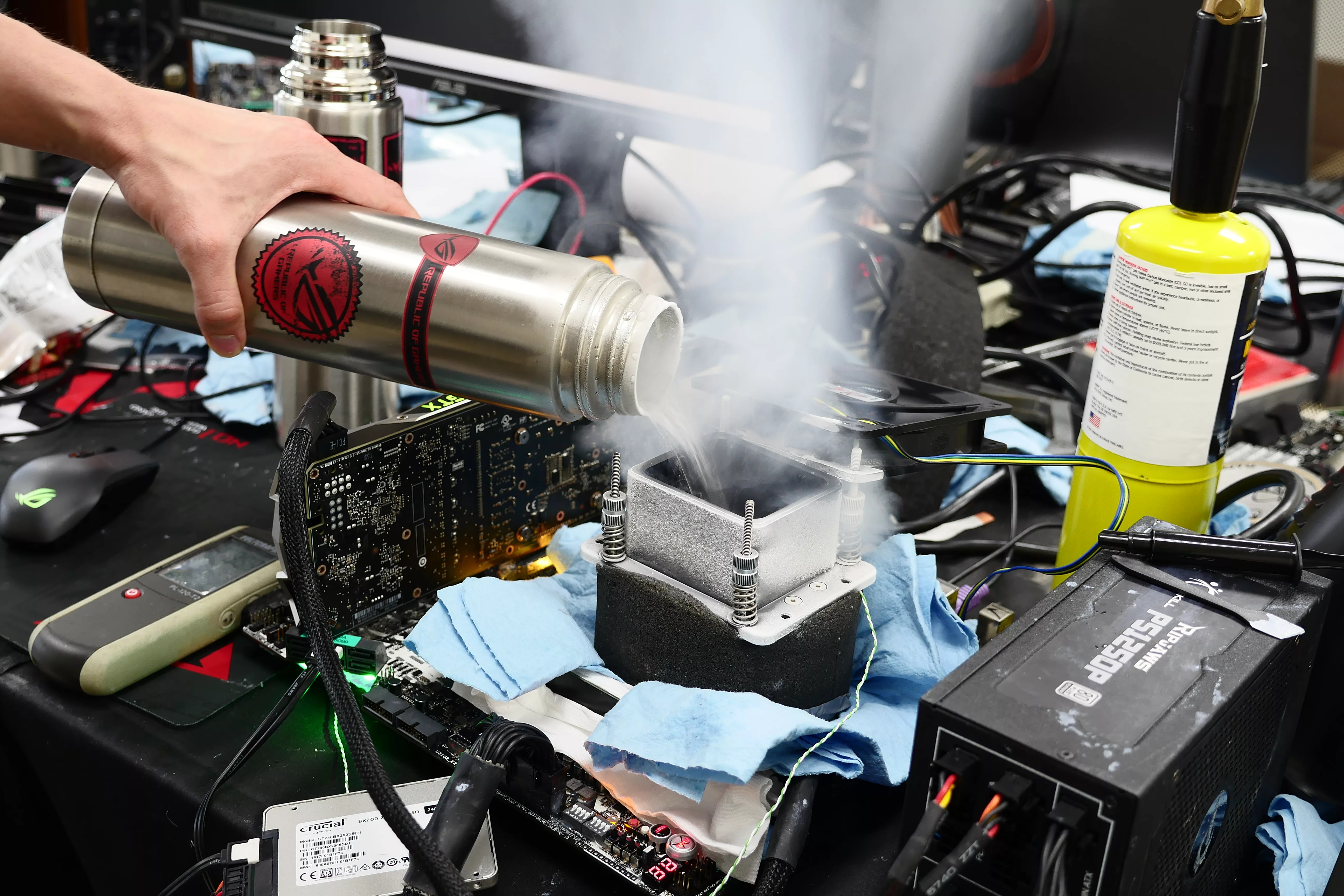
The Rampage VI Apex claims more performance victories with Intel's new Core i9-7940X and i9-7980XE
After dominating extreme overclocking with the first wave of Skylake-X CPUs, we've taken the latest 14- and 18-core models to sub-zero extremes.